
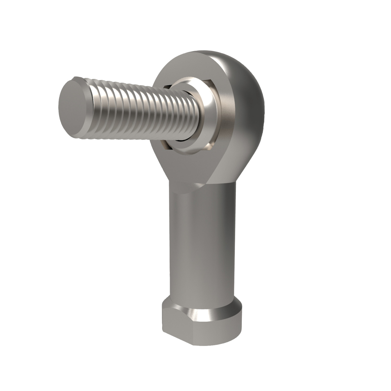
Rod Ends With Stud From Automotion
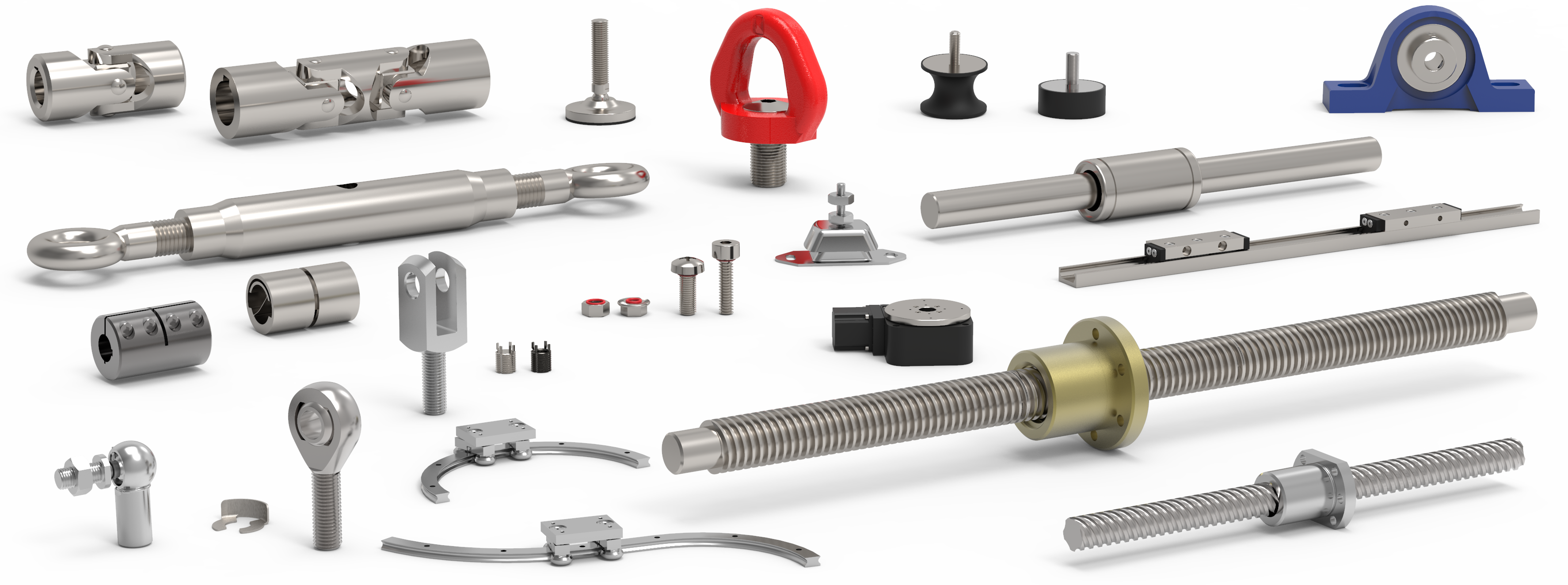
Our range of linkages and joints provides a wide range of solutions for providing connections in machinery in a variety of applications. Whether you need universal joints to connect shafts across an angle discrepancy or clevis joints for connecting to rods, we can provide you with the technical assistance and data you need for your application. We have both metric and inch sizing products where available.
Our range of anti-stiction air cylinders complements our range of linkages by providing smooth and efficient operation of applications attached to the joint.
Be sure to request your free catalogue here today and make use of our freely available CAD files on each product page.


Maintenance free. Sizes according to DIN ISO 12740-4, series K

Maintenance free, sizes according to DIN ISO 12230-4 series K.


Maintenence free, sizes according to DIN ISO 12240-4 series K
Associated Products
Technical Specs
Rod end bearings load capacity explained
Static load capacity C0(plain bearings)
The static load capacity C0 is the radially acting static load which does not cause any permanent deformation of the components when the spherical bearing or rod end is stationary, (i.e. the load condition without pivoting, swivelling or tilting movements). It is also a precondition here that the operating temperature must be at normal room temperature and the surrounding components must possess sufficient stability.
The values specified in the tables are determined by static tension tests on a representative number of series components at 20°C normal room temperature. The static load capacity may vary with lower or higher temperature depending on the material. In the case of all rod ends with plain bearings, the static load rating refers to the maximum permissible static load of the rod end housing in a tensile direction up to which no permanent deformation occurs at the weakest housing cross-section. The value in the product tables has a safety factor of 1.2 times the tensile strength of the rod ends housing material.
Static load capacity C0(roller and ball bearings)
For our rod ends with roller and ball bearings, the static load rating is the load at which the bearing can operate at room temperature without its performance being impaired as a result of deformations, fracture, or damage to the sliding contact surfaces (max 1/10,000th of the ball diameter).
Dynamic load capacity C (plain bearings)
Dynamic load ratings serve as values for calculation of the service life of dynamically-loaded spherical bearings and rod ends. The values themselves do not provide any information about the effective dynamic load capacity of the spherical bearing or rod end. To obtain this information, it is necessary to take into account the additional influencing factors such as load type, swivel or tilt angle, speed characteristic, max. permitted bearing clearance, max. permitted bearing friction, lubrication conditions and temperature, etc.
Dynamic load capacities depend on the definition used to calculate them. Comparison of values is not always possible owing to the different definitions used by various manufacturers, and because the load capacities are often determined under completely different test conditions.
Dynamic load capacity C (roller and ball bearings)
For our rod ends with roller and ball bearings, the dynamic load capacity is the load at which 90% of a large quantity of identical rod ends reach 1 million revolutions before they fail (due to fatigue of the rolling surfaces.)
Operating Temperatures
Heavy-duty ball and roller bearin rod ends can be used for operating temperatures between -20oC and +120oC. The temperature range of heavy-duty rod ends with integral spherical plain bearing is between -30oC and +60oC, without affecting the load capacity. Higher temperatures will reduce the load capacity taken into account for the calculation of the 'working life' under the temperature factor C2 on page 116.
Loads
The decisive parameters for the selection and calculation of heavy-duty rod ends are size, direction and type of load
Radial or combined loads
The heavy-duty rod ends have been especially designed to cope with high radial loads. They can be used for combined loads, theaxial load share of which does not exceed 20% of the corresponding radial load.
Unilaterally acting load
In this case the load acts only in the same direction, which means that the load area is always in the same bearing section.
Alternately acting load
In case of alternating loads, the load areas facing each other are alternately loaded and/or relieved, which means that the load changes its direction constantly by approximately 180o.

Radial or combined loads

Unilaterally acting load

Alternately acting load
Swivelling Angle
The swivelling angle is the movement of the rod end from one final position to the other. Half the swivelling angle a3 is used to calculate the service of 'working life'.

Angle of tilt
Thje anfle of tilt, also called setting angle, refers to the movement of the joint ball and/or the inner ring to the rod end axis (in degrees). The tilting angle (a) indicated in the table for the heavy-duty ball and roller bearing rod ends corresponds to the maximum possible movement being limited by the shields on both sides.
It is important that this tilting angle is not exceeded either during installation or operation, as operation, as otherwise the shields may be damaged. For heavy-duty plain bearing rod encds a distiction is made between the tilting angles (a1 and a2).
If the movement is not limited by adjacent components, then angle a1 can fully be used without affecting the rod end capacity. Tilting angle a2 is the movement limit when connecting a forked component.


Nominal service life
The term ‘nominal service life’ is used for heavy-duty ball and roller bearing rod ends and represents the number of swivelling motions or rotations and/or the number of service hours the rod end performs before showing the first signs of material fatigue on the raceway or roller bodies. In view of many factors that are difficult or impossible to assess, the service life of several apparently identical bearings differ under the same operating conditions.
For this reason, the following method for the service life determination of heavy-duty ball and roller rod ends results in a nominal service life being achieved or exceeded by at least 90% of a large quantity of identical rod ends.
Working Life
The term ‘working life’ is used with heavy-duty plain bearing rod ends. It represents the number of swivelling motions or rotations and/ or the number of service hours the heavy duty plain bearing rod end performs before becoming unserviceable due to material fatigue, wear, increased bearing clearance or increase of the bearing friction moment.
The ‘working life’ is not only influenced by the size and the type of load, it is also affected by a number of factors, which are difficult to assess. A calculation of the exact service life is therefore impossible. Field-experienced standard values for the approximate ‘working life’ can nevertheless be determined by using the following calculation procedure which is based on numerous results from endurance test runs and values from decades of experience. The values determined by this formula are achieved, if not exceeded, by the majority of the heavy-duty rod ends.
Heavy-duty rod ends
R3550, R3551, R3556, R3557, R3561, R3562, R3563, R3564, R3565, R3566, R3610, R3611, R35613, R3616
| d1Over | d1icl. | d1mp Tolerance LimitUpper | d1mp Tolerance LimitLower | Vd1pMax. | Vd1mpMax. | b1s Tolerance LimitUpper | b1s Tolerance LimitLower | hs, h1s, h2s Tolerance LimitUpper | hs, h1s, h2s Tolerance LimitLower |
| 6 | +0,012 | 0 | 0,012 | 0,009 | 0 | -0,12 | +0,8 | -1,2 | |
| 6 | 10 | +0,015 | 0 | 0,015 | 0,011 | 0 | -0,12 | +0,8 | -1,2 |
| 10 | 18 | +0,018 | 0 | 0,018 | 0,014 | 0 | -0,12 | +1,0 | -1,7 |
| 18 | 30 | +0,021 | 0 | 0,021 | 0,016 | 0 | -0,12 | +1,4 | -2,1 |
| 30 | 50 | +0,025 | 0 | 0,025 | 0,019 | 0 | -0,12 | +1,4 | -2,7 |
Heavy-duty rod ends
R3553, R3554, R3559, R3560, R3567, R3568
| d1Over | d1icl. | d1mp Tolerance LimitUpper | d1mp Tolerance LimitLower | Vd1pMax. | Vd1mpMax. | b1s Tolerance LimitUpper | b1s Tolerance LimitLower | hs, h1s, h2s Tolerance LimitUpper | hs, h1s, h2s Tolerance LimitLower |
| 10 | +0,002 | -0,010 | 0,008 | 0,006 | 0 | -0,12 | +0,8 | -1,2 | |
| 10 | 18 | +0,003 | -0,011 | 0,008 | 0,006 | 0 | -0,12 | +0,8 | -1,2 |
| 18 | 30 | +0,003 | -0,013 | 0,010 | 0,008 | 0 | -0,12 | +1,0 | -1,7 |
| 30 | 50 | +0,003 | -0,015 | 0,012 | 0,009 | 0 | -0,12 | +1,4 | -2,1 |
| 50 | 80 | +0,004 | -0,019 | 0,015 | 0,011 | 0 | -0,15 | +1,8 | -2,7 |
Dimensions and tolerance symbols
d1 = Nominal bore diameter of the inner ring or joint ball
d1mp = mean bore diameter deviation in one plane, arithmetical mean of the largest and smallest bore diameter
Vd1p = Bore diameter variation in one plane, difference between the largest and smallest bore diameter.
Vd1mp of = Mean bore diameter variation, difference between the largest and smallest bore diameter. One inner ring or joint ball.
b18 = Singe inner ring or joint ball width deviation
h, h1, h2 = Single length from the inner ring or ball bore centre to shank end
h8 h18 h82 = Single length variation of a single rod end